LED and Sensor Integration in VehiclesOSP Combines Lighting, Sensors, and Actuators
A guest post by
Florian M. Kolb* | Translated by AI
8 min Reading Time
Numerous light sources, distributed sensors, and central vehicle computers place new demands on what is known as the “last mile” of the vehicle network. The Open System Protocol is designed to connect LEDs, I²C components, and other actuators via a common, cost-effective interface.
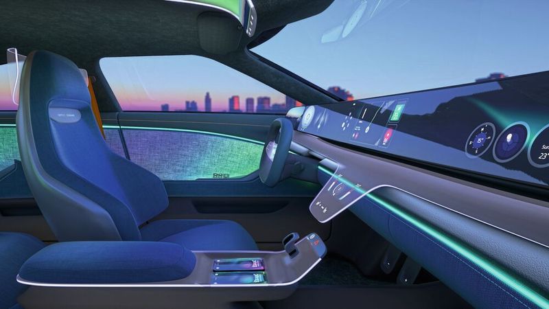
Open System Protocol: The concept of a vehicle interior with distributed, dynamic RGB lighting.
(Image: AMS Osram)
Unlike conventional vehicle architectures, which feature a large number of distributed electronic control units (ECUs), modern architectures are increasingly relying on centralized control units. This makes it easier to implement software-defined functions and software updates, while also reducing the complexity of the vehicle’s software landscape.
The centralized control units are connected via a network backbone, typically through high-speed Ethernet networks. However, for cost reasons, individual sensors or actuators—such as a rotational speed sensor, an electric motor, or light-emitting diodes with their associated drivers—cannot each be equipped with an Ethernet interface. This would require, among other things, an Ethernet transceiver, a microcontroller, and a network stack. Therefore, the vehicle data available via Ethernet must be converted in the respective control units or network distributors—known as zone controllers—into adapted and cost-effective interfaces for the so-called “last mile.” This refers to the connection from the vehicle network to a single component or a small group of components.
Existing automotive interfaces such as LIN or CAN are frequently used for this “last mile.” However, they are only partially suitable for new and more demanding in-vehicle applications—for example, due to their limited data rate, the limited number of addressable components, or the need for a local microcontroller to manage communication.
Dynamic Interior Lighting and the Vehicle's Electronics
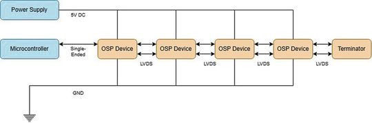
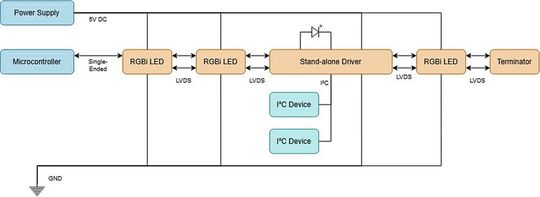
Figure 1: OSP daisy-chain topology with single-ended communication between the microcontroller and the first OSP device, and LVDS communication between the remaining OSP devices. Addressing occurs automatically during initialization: An INIT telegram is forwarded to the next OSP device, which increments the device address.
(Image: AMS Osram)
One example of an advanced automotive application with new requirements for data interfaces is interior or ambient lighting. In the past, this was typically a functional application with only a few light sources.
Thanks in part to the capabilities of modern LED technology, interior lighting has become a key factor in comfort and brand differentiation. Among other things, the following requirements apply to its use:
a large number of light sources,
coverage of a wide range of the RGB spectrum, partially supplemented by white emitters,
high absolute and relative color consistency among the individual light sources under various environmental conditions—and particularly under different temperature conditions,
the dynamic, real-time adjustment of lighting parameters—such as brightness or color—synchronized throughout the entire vehicle interior.
Existing data interfaces such as LIN or CAN can only meet these requirements with additional effort. For example, the available data rate of LIN may not be sufficient to control a large number of light points. Distributing the load across multiple LIN buses then requires additional hardware and software layers and complicates temporal synchronization.
CAN and Ethernet can also involve significant effort in applications that sometimes include several hundred individual light points, due to the hardware and software required. In addition, there are proprietary solutions that require specific components and, as a result, may also depend on a specific supply chain.
The Open System Protocol (OSP)
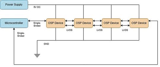
Figure 2: OSP topology with loopback. The last OSP device is connected to a second I/O pin on the microcontroller. This can improve reliability and reduce response times, especially in long chains.
(Image: AMS Osram)
One interface for this application is the Open System Protocol (OSP), developed by AMS Osram. This is an interface standard whose specifications are publicly available and which has been submitted to ISO for standardization.
OSP functions as a commander-responder interface in a daisy-chain topology. The components are connected to one another via an interference-resistant, LVDS-based interface. The central controller sends commands in the form of telegrams to the first component in the chain. If the destination address in the telegram matches the address of that component, it executes the command. Otherwise, it forwards the telegram to the next component in the chain. A response from the target component is transmitted back to the controller via the chain.
The daisy-chain topology also enables automatic addressing during initialization of the OSP system. To achieve this, the respective OSP address is passed from one component to the next, where it is incremented. For use as a light bus, RGB LEDs with integrated OSP-compatible drivers are used, among other components.
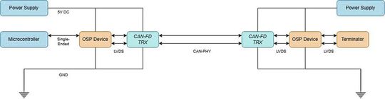
Figure 3: Use of CAN-FD transceivers to bridge longer distances, such as between two separate printed circuit boards.
(Image: AMS Osram)
In addition to a chain with a terminator on the last element, a loopback topology is also possible. In this configuration, the last element is connected to the controller via a second interface. This can improve reliability, since each component is, in principle, accessible from both directions. In long chains, response time can also be reduced because response telegrams can be sent back to the controller via the shorter section of the chain. According to the manufacturer, OSP can address up to 1,000 components in a chain. For example, 100 LEDs can be driven at a refresh rate of more than 100 Hz. A CAN-FD transceiver can be used to bridge longer distances. It serves to convert the standard LVDS physical layer of OSP to a CAN-FD physical layer.
Date: 08.12.2025
Naturally, we always handle your personal data responsibly. Any personal data we receive from you is processed in accordance with applicable data protection legislation. For detailed information please see our privacy policy.
Consent to the use of data for promotional purposes
I hereby consent to Vogel Communications Group GmbH & Co. KG, Max-Planck-Str. 7-9, 97082 Würzburg including any affiliated companies according to §§ 15 et seq. AktG (hereafter: Vogel Communications Group) using my e-mail address to send editorial newsletters. A list of all affiliated companies can be found here
Newsletter content may include all products and services of any companies mentioned above, including for example specialist journals and books, events and fairs as well as event-related products and services, print and digital media offers and services such as additional (editorial) newsletters, raffles, lead campaigns, market research both online and offline, specialist webportals and e-learning offers. In case my personal telephone number has also been collected, it may be used for offers of aforementioned products, for services of the companies mentioned above, and market research purposes.
Additionally, my consent also includes the processing of my email address and telephone number for data matching for marketing purposes with select advertising partners such as LinkedIn, Google, and Meta. For this, Vogel Communications Group may transmit said data in hashed form to the advertising partners who then use said data to determine whether I am also a member of the mentioned advertising partner portals. Vogel Communications Group uses this feature for the purposes of re-targeting (up-selling, cross-selling, and customer loyalty), generating so-called look-alike audiences for acquisition of new customers, and as basis for exclusion for on-going advertising campaigns. Further information can be found in section “data matching for marketing purposes”.
In case I access protected data on Internet portals of Vogel Communications Group including any affiliated companies according to §§ 15 et seq. AktG, I need to provide further data in order to register for the access to such content. In return for this free access to editorial content, my data may be used in accordance with this consent for the purposes stated here. This does not apply to data matching for marketing purposes.
Right of revocation
I understand that I can revoke my consent at will. My revocation does not change the lawfulness of data processing that was conducted based on my consent leading up to my revocation. One option to declare my revocation is to use the contact form found at https://contact.vogel.de. In case I no longer wish to receive certain newsletters, I have subscribed to, I can also click on the unsubscribe link included at the end of a newsletter. Further information regarding my right of revocation and the implementation of it as well as the consequences of my revocation can be found in the data protection declaration, section editorial newsletter.
RGB LED with an OSP-Compatible Driver
The CAN-FD physical layer also allows for the creation of a star topology. To do this, multiple subnets—each with its own transceiver—are connected to a CAN-FD bus. A subnet address is defined at the beginning of each subnet using standalone drivers. The subsequent components are automatically assigned an address during initialization.
One possible standard component for OSP networks is an RGB LED with an integrated OSP-compatible driver that can be incorporated into a chain without any additional external components. Since the calibration data for each individual LED is already stored in the driver, there is no need for subsequent color measurement and calibration during the manufacturing process.
To control LEDs of other colors or types via OSP, standalone drivers can be used. They allow for the connection of up to nine individual LEDs or three RGB LEDs. Examples include special types such as RGB side-emitting LEDs, LEDs with specific colors, or LEDs with different shades of white.
According to the manufacturer, the chip design and pinout were engineered to eliminate the need for a multilayer printed circuit board. Compared to solutions using multilayer printed circuit boards, this can reduce PCB complexity and facilitate integration into flexible printed circuit boards.
Distributed Sensors and Actuators with OSP
Figure 4: Stand-alone driver for OSP for controlling any LEDs and connecting I²C components. These can be controlled and read via OSP.
(Image: AMS Osram)
OSP can be used for more than just a lighting bus. In addition to LED control, the stand-alone drivers have another feature that expands the interface’s range of applications: For each driver, three LED control lines can be configured together as an I²C interface with a clock line (SCL), a data line (SDA), and an interrupt line (INT).
This allows I²C components to be integrated into an OSP chain without an intermediate microcontroller. Distributed sensors or actuators can thus be placed wherever an OSP interface is already available nearby. In this case, no additional wires to a local microcontroller are required.
Examples of how to integrate I²C components into OSP can be found in the OSP Evaluation Kit, which is available from various electronics distributors. In addition to I²C EEPROMs for storing color and animation data, as well as temperature and ambient light sensors, the Evaluation Kit includes Hall-effect encoders as position sensors. Conventional pushbuttons and indicator lights are also connected via I²C I/O expanders.
One possible application is measuring temperatures at multiple locations inside the vehicle to assist with climate control. Light and color sensors can be used to adjust interior lighting and displays to the ambient brightness and the current lighting conditions.
The components can be combined with RGB LEDs in the OSP chain. Thanks to automatic addressing during initialization, OSP addresses are automatically assigned to both the LEDs and the standalone drivers via their I²C interface. AMS Osram provides software examples on GitHub for general use of OSP and for integrating I²C components with OSP.
Connection to the Vehicle Network
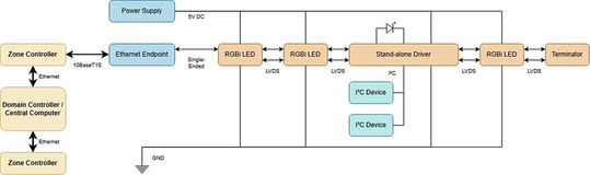
Figure 5: Connecting OSP to the vehicle's Ethernet network via an Ethernet endpoint.
(Image: AMS Osram)
OSP offers control options beyond just the component level. Since modern vehicle architectures are often based on an Ethernet backbone, an interface between Ethernet and OSP is also of practical importance. In addition, OSP can be connected via a local control unit or a zone controller equipped with an automotive microcontroller. Another option is the use of so-called Ethernet endpoints. These are small, fixed-programmed modules that provide an Ethernet interface on one side for connection to the vehicle network and one or more local last-mile interfaces on the other.
Using a remote control protocol, such as IEEE 1722, data can be encapsulated in Ethernet packets to and from the local interfaces. This allows the local interfaces to be connected to a centralized processing unit via the vehicle network.
This is of particular interest in connection with the 10BASE-T1S Ethernet standard. The standard enables Ethernet connections over a two-wire line and can thus support the use of Ethernet within the vehicle. According to AMS Osram, several manufacturers of microcontrollers and Ethernet endpoints have already developed products designed to connect to OSP. A list of these products is available on the manufacturer’s OSP website.
Applications for Exterior Vehicle Lighting
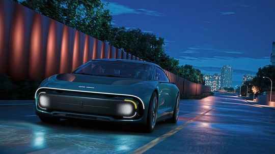
Figure 6: Dynamic exterior vehicle lighting with OSP.
(Image: AMS Osram)
Future additions and enhancements to OSP could also open up applications in exterior vehicle lighting. These include, for example, specialized drivers designed to meet ASIL requirements that are connected to a microcontroller or endpoint via UART. In addition to conventional signal lighting, potential applications include, in particular, body and grille lighting. These include dynamic lighting effects to enhance brand identity, as well as convenience features such as welcome animations.
Another application is what are known as intelligent signal displays. They can be used to communicate with other road users or to show the driver information—such as the vehicle battery’s charge level—even before getting in the car.
Outlook
Supply chain reliability is crucial, particularly in the automotive sector. An open and standardized protocol can simplify the selection of components and suppliers. According to AMS Osram, OSP was developed as an open and vendor-neutral protocol. Furthermore, OSP has been undergoing standardization since February 2026 as part of the ISO Working Group ISO/TC 22/SC 31/WG 3, which helps to promote support for the protocol in the automotive and industrial sectors.
OSP is designed as an open interface for the "last mile" between the central processing unit and distributed components. In addition to lighting, it can also be used to connect sensors and actuators in distributed applications. The combination of daisy-chain topology, automatic addressing, and the ability to integrate I²C components without a local microcontroller addresses applications with a large number of distributed components.
*Florian M. Kolb is responsible for Application Business Development at AMS Osram



:quality(80)/p7i.vogel.de/wcms/81/d4/81d47ab5407c961b55233009313ac9d2/0133075510v1.jpeg "Small, but designed for demanding applications: KSK demonstrates that the diameter of ball screws says nothing about their load-carrying capacity. (Image:Arkero)")
:quality(80)/p7i.vogel.de/wcms/6b/80/6b80bac3b1b33a0e3bc17849bef4ba59/0133171618v1.jpeg "With its portal solution for the MAK 4 Evolution UD swivel-bending machine, Schröder enables the fully automated production of sheet-metal enclosures. (Image:Schröder Group)")
:quality(80)/p7i.vogel.de/wcms/a0/1d/a01ddede6a787a4844122c2f42cfbce9/0133067101v1.jpeg "In solar module manufacturing, lasers are used for tasks such as patterning, drilling, and cutting delicate layers. Precise energy delivery is crucial to avoid damaging adjacent areas. (Image:Dall-E / AI-generated)")
:quality(80)/p7i.vogel.de/wcms/6c/98/6c98f4dd0780456713eee6379b3f534f/0132999605v1.jpeg "This specific project involved a similar surgical screw. (Image:KLS Martin)")
:quality(80)/p7i.vogel.de/wcms/ff/45/ff451109015c2f01b67ad3b0bad321ea/werma-success-story-skanska-1v1.webp "WeAssist combines traditional signal towers with a smart cloud solution. This allows the different colors of the signal towers to facilitate clear and intuitive communication during operations. (Source: Werma)")
:quality(80)/p7i.vogel.de/wcms/86/b1/86b14463fdbf6e77cafa6709433114bf/0132830551v1.jpeg "A look inside the automated testing lab at Amag Austria Metall AG's SmartFactory. (Image:Amag Austria Metall AG)")
:quality(80)/p7i.vogel.de/wcms/29/a8/29a8ea15ab38e4404bc1c6a3e425e454/adobestock-1550141473--leopard-stock-adobe-com-ki-generiertv1.jpeg "When Machines Understand What They're Doing—The Five Technologies Behind Physical AI. (Source: © Leopard – stock.adobe.com_AI-generated)")
:quality(80)/p7i.vogel.de/wcms/a0/0c/a00c9b7242fa38414b3281a9cd6dcc39/0133127938v1.jpeg "Demand for electronics and semiconductor products is expected to continue growing, prompting manufacturers to innovate and ramp up production while overcoming challenges. (Image:Siemens)")
:quality(80)/p7i.vogel.de/wcms/92/e9/92e9f029ef416e02b6f0b772b39c30df/limbitless-stratasys-zacharyv1.jpeg "The renewed focus of the expanded partnership between Stratasys and Limbitless is on sustainability, education, and improved access to 3D-printed prosthetics. (Source: Stratasys)")
:quality(80)/p7i.vogel.de/wcms/01/f1/01f16ebdc19b9cbde5bc1a7f421f9174/csm-a264340-web-1440-d0360d8de9v1.webp "At the 2026 Dutch Grand Prix in late August, two filtration systems developed by TU Berlin were used in top-level motorsports for the first time. (Source: Audi Revolut F1 Team)")
:quality(80)/p7i.vogel.de/wcms/00/c3/00c3f0f623f1b22935c99a2d364e2b6f/4082x2406v1.jpeg "EPFL researchers have unveiled ScaFi (short for “Scalable Fish”), a robot modeled after fish such as cod and mackerel. Its size can be adjusted as needed. (2026 CREATE Lab EPFL)")
:quality(80)/p7i.vogel.de/wcms/fd/76/fd76fd67142ded48cfcb2e819bea231b/0133154160v1.jpeg "The pacemaker implant is flexible and conforms to the shape of the brain. This significantly improves comfort. (Image:Fraunhofer IZM)")
:quality(80)/p7i.vogel.de/wcms/9e/6e/9e6eadbb44711dca055482f29b651ca9/0133192930v1.jpeg "At Automechanika, Stellantis' SUSTAINera business unit is introducing a remanufactured NOx sensor. (Image:Stellantis)")
:quality(80)/p7i.vogel.de/wcms/8d/f0/8df02ef9301116199dd602a1b3ffa976/0133198864v1.jpeg "Open System Protocol: The concept of a vehicle interior with distributed, dynamic RGB lighting. (Image:AMS Osram)")
:quality(80)/p7i.vogel.de/wcms/3a/52/3a524cf069c88cbd661c88d4a49f864f/db2022fa00082-largev1.jpeg "How much longer will VW models continue to be built in Emden? (Source: Volkswagen AG)")
:quality(80)/p7i.vogel.de/wcms/d5/49/d549f4999960da7667d46c23e68f31b9/denza-z9gt-03detail-062v1.jpeg "Some companies in China are competing to offer the shortest charging time. (Image:BYD)")
:quality(80)/p7i.vogel.de/wcms/22/32/223265897c761a5ec2207a53151d2a36/adobestock-2168933153--zmaj88-stock-adobe-com-ki-generiertv1.jpeg "The 800-VDC power distribution system has established itself as a practical way to efficiently supply power to racks, even at the megawatt level. (Source: © zmaj88 – stock.adobe.com / AI-generated)")
:quality(80)/p7i.vogel.de/wcms/7d/a3/7da3623df87775722e9ba4fda7e16dc7/0133164888v1.jpeg "Z.ai told ChatGPT how it would like to be portrayed. (Image:Dall-E / AI-generated)")
:quality(80)/p7i.vogel.de/wcms/88/62/886275be9b95f912061e9d7e77a3b799/0133171501v1.jpeg "Secure and reliable cloud platforms for businesses have long since become a strategic decision. (Image:Pixabay / Brian Penny / AI-generated)")
:quality(80)/p7i.vogel.de/wcms/0d/da/0dda2dc67d266b0577dd243f8e6321dd/0133153751v1.jpeg "The rising demand for AI infrastructure is having a direct impact on the supply chain and exposing bottlenecks in production. (Image:Broadcom)")
:quality(80)/p7i.vogel.de/wcms/ee/dc/eedc0c644f450569196251abb50015d7/0129550734v1.jpeg "The Open System Protocol from ams Osram for dynamic lighting applications and intelligent vehicle networks is to be implemented as an ISO standard in the future. (Image:ams Osram)")
:quality(80)/p7i.vogel.de/wcms/66/72/66727bd681ea686728d92c34c945696a/0127890956v1.jpeg "Microchip Technology has introduced the LAN866x family of 10BASE-T1S endpoints with Remote Control Protocol. (Image:Microchip)")