Alternative to ShootersHow to Reduce the Space Required for High-Current Switches
By
Takato Nabeshima* | Translated by AI
5 min Reading Time
PCB relays with higher current-carrying capacity and integrated fault detection offer an alternative to contactors for rated currents ranging from 50 to 300 A. Here’s what you need to keep in mind when making the switch.
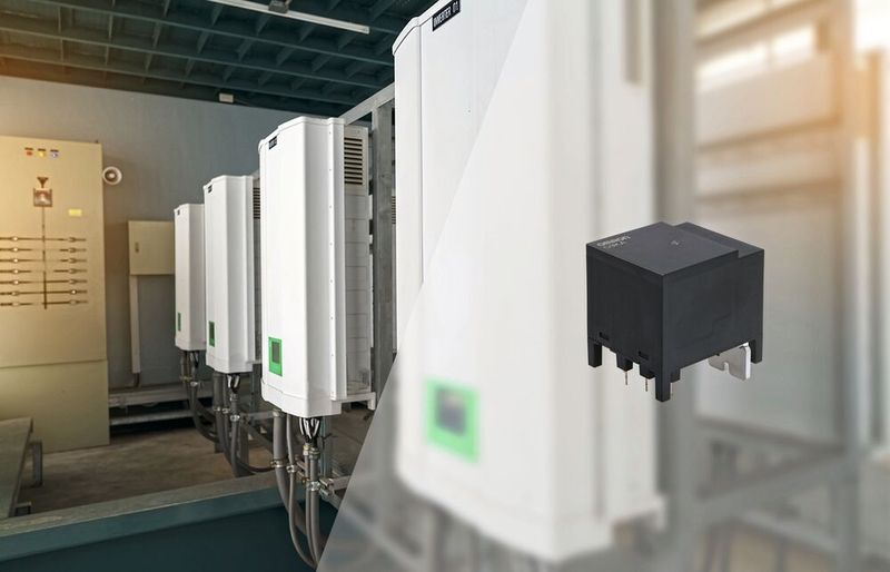
Contactors vs. High-Current Relays: Contactors are considered the “kings” of high-current switching. However, high-current relays are now also making their mark in this area.
(Image: Omron)
The trend toward electrification is driving up demand for upgrades and modernizations across all infrastructure—from solar and wind power plants to end-use locations. Power control is a crucial aspect of this. Devices intended for use in residential buildings face significant cost pressures. Miniaturization is required to enable unobtrusive designs. In industrial electrification, on the other hand, reliability and error handling are the primary requirements. Advances in efficiency, however, are in demand everywhere.
Switching High Currents: Contactors vs. Relays
When it comes to handling high currents and voltages, electromechanical switches such as contactors and relays are the preferred choice. This is because they offer high rated values and safely isolate inactive loads.
Gallery
Contactors typically have larger electromagnetic coils than relays, as well as spring-loaded contacts for breaking the circuit. They are primarily used in applications where extremely high currents must be controlled. Contactors also typically feature built-in detection to determine whether the contacts have welded together. This prevents the main contacts from becoming stuck and unable to open. This is usually achieved using a set of auxiliary contacts that mirror the main contact structure.
Due to their auxiliary contact mechanism, higher coil power, and spring force, contactors are generally larger than elementary relays and have a lower maximum switching frequency. Connections are typically made via screw terminals, which must be installed manually.
In today's electrified world, new direct current (DC) switching applications include large inverters for photovoltaic generators and battery energy storage systems in the power grid, high-speed EV chargers and wall boxes, as well as uninterruptible power supplies (UPS).
These new applications are turning the old order upside down and require the high current-carrying capacity and safety features of contactors, but with a smaller size and lower power consumption in devices that are compatible with mass-production techniques. Similar requirements apply to alternating current (AC) loads such as lighting, heating, ventilation, and cooling, and factory automation, where power density is increasing and the need for smaller and more compact devices is growing.
When Relays Switch Higher Loads
New developments in relay technology enable rated currents ranging from 50 to 300 A. As a result, these components offer an alternative to contactors in many residential, industrial, and utility applications. Current components also detect welded contacts and issue a fault message, thereby providing comparable system protection. The auxiliary contact mechanism shown in Figure 1 ensures reliable isolation with a dielectric strength of 2.5 kV or a minimum contact gap of 0.5 mm (approximately 0.020 in), even after the coil has been de-energized, should the main contacts weld together.
Among the inherent advantages of relays are smaller component dimensions, which allow for more compact and flatter housings. This is equally important for consumer applications as well as for industrial and power supply applications, which face the challenge of installing more and smarter infrastructure amid increasing space constraints. A comparison of the characteristics of a typical contactor with those of a comparable relay shows a weight reduction of more than 66%, as well as a height reduction of more than 60% and a volume reduction of 85%.
The smaller size and generally lower weight of elementary relays allow high-power switches to be mounted on the printed circuit board, which simplifies device assembly and makes it more efficient.
Printed circuit board assemblies are compatible with automated production processes, allowing circuits to be assembled at high speeds using in-line placement machines. Through subsequent automated soldering, device manufacturers can eliminate the need for conventional, bulky, and expensive components such as busbars and screw terminals, which must be fastened manually. In addition to faster and more efficient assembly, soldered connections prevent human errors such as incomplete tightening of screws or incorrect torque, resulting in more consistent production quality.
Date: 08.12.2025
Naturally, we always handle your personal data responsibly. Any personal data we receive from you is processed in accordance with applicable data protection legislation. For detailed information please see our privacy policy.
Consent to the use of data for promotional purposes
I hereby consent to Vogel Communications Group GmbH & Co. KG, Max-Planck-Str. 7-9, 97082 Würzburg including any affiliated companies according to §§ 15 et seq. AktG (hereafter: Vogel Communications Group) using my e-mail address to send editorial newsletters. A list of all affiliated companies can be found here
Newsletter content may include all products and services of any companies mentioned above, including for example specialist journals and books, events and fairs as well as event-related products and services, print and digital media offers and services such as additional (editorial) newsletters, raffles, lead campaigns, market research both online and offline, specialist webportals and e-learning offers. In case my personal telephone number has also been collected, it may be used for offers of aforementioned products, for services of the companies mentioned above, and market research purposes.
Additionally, my consent also includes the processing of my email address and telephone number for data matching for marketing purposes with select advertising partners such as LinkedIn, Google, and Meta. For this, Vogel Communications Group may transmit said data in hashed form to the advertising partners who then use said data to determine whether I am also a member of the mentioned advertising partner portals. Vogel Communications Group uses this feature for the purposes of re-targeting (up-selling, cross-selling, and customer loyalty), generating so-called look-alike audiences for acquisition of new customers, and as basis for exclusion for on-going advertising campaigns. Further information can be found in section “data matching for marketing purposes”.
In case I access protected data on Internet portals of Vogel Communications Group including any affiliated companies according to §§ 15 et seq. AktG, I need to provide further data in order to register for the access to such content. In return for this free access to editorial content, my data may be used in accordance with this consent for the purposes stated here. This does not apply to data matching for marketing purposes.
Right of revocation
I understand that I can revoke my consent at will. My revocation does not change the lawfulness of data processing that was conducted based on my consent leading up to my revocation. One option to declare my revocation is to use the contact form found at https://contact.vogel.de. In case I no longer wish to receive certain newsletters, I have subscribed to, I can also click on the unsubscribe link included at the end of a newsletter. Further information regarding my right of revocation and the implementation of it as well as the consequences of my revocation can be found in the data protection declaration, section editorial newsletter.
Switch to High-Current PCB Relays
The transition from established design practices and production processes—which previously relied on traditional, manually assembled contactors—to relay assemblies for printed circuit board (PCB) mounting literally requires a return to hand-drawn design to create a new PCB layout. PCB design guidelines include ensuring sufficient copper thickness to carry the intended current levels. Increasing the pad size helps improve heat dissipation.
In applications that require extremely high current levels, a heat sink or an insulated metal substrate helps protect the printed circuit board. Furthermore, for high-power PCB relays, implementing a hold-up circuit or a PWM drive circuit to minimize power consumption can effectively simplify thermal management and potentially reduce the drive power by 25%.
Electronics manufacturers can offset the investment in redesigning their printed circuit boards by increasing sales through the offering of smaller, lighter PCB assemblies that meet market demands.
The production area may also need to be restructured to reduce or eliminate manual workstations and switch production to automated machines for through-hole assembly. A comparison of manufacturing techniques shows that soldered connections can reduce the bill of materials (BOM)—including busbars and screws—by up to 35% and lower the costs of the assembly process by up to 50%. The benefits of automated assembly become even more significant as production volumes increase.
In addition, switching to PCB relays can boost product performance and improve energy efficiency. Their lower contact resistance results in reduced I2R losses and less heat dissipation, which increases contact reliability. The lower coil power also contributes to higher efficiency.
Among the high-current PCB relays is the single-pole G9KA-1A1B-E, which can switch currents up to 300 A and has a contact resistance of less than 0.2 mΩ. The design and selected materials contribute to the low resistance and also enable a contact spacing of 4.0 mm (approximately 0.16 in), ensuring high performance while maintaining safety. Integrated 30 V/1 A mirror contacts enable the detection of contact welding in accordance with IEC 60947-4-1, the international standard for electromechanical contactors and starters, including motor protection switches.
Overall, while the transition to printed circuit board assembly requires an initial investment, suppliers benefit significantly in the long term from cost savings as well as greater efficiency and reliability.
More Compact and Cost-Effective Power Control
Circuit breakers have long been considered the “kings” of high-current switching and cover a wide range of rated currents up to several hundred amperes. Among their strengths are auxiliary contacts for fault detection. Disadvantages include the large and heavy coil and the corresponding closing mechanism, which require a lot of space and limit the switching frequency. Manual assembly processes slow down production and leave room for human error.
New requirements are driving developments in PCB relays. This opens up a new option for rated currents ranging from 50 to 300 A, enabling more compact, reliable, efficient, and cost-effective power control.
*Takato Nabeshima is the Product Marketing Manager for Relays at Omron Electronic Components Europe in Hoofddorp, Netherlands



:quality(80)/p7i.vogel.de/wcms/5e/f8/5ef8d3b9a25951f1b4a3fac0f4b65281/0133131043v1.jpeg "Kasto has significantly improved its long-proven Kastossb automatic band saw and will be showcasing it at the upcoming AMB. For example, it now features an electromechanical saw feed mechanism that reduces energy consumption. Read here to find out what other new developments there are in the world of sawing ... (Image:Kasto)")
:quality(80)/p7i.vogel.de/wcms/43/bc/43bcc092db07947d7f240564e7d8549d/0133068647v1.jpeg "The C80 Giga inductive coupling system from SMW transmits power up to 75 W—and signals in real time at speeds of up to 1 GBit/s. (Image:SMW-Autoblok / SMW-electronics)")
:quality(80)/p7i.vogel.de/wcms/bd/b6/bdb6acbb7eafcbb21fcf66f8835ccb6d/0132925320v1.jpeg "Kyocera's MG90B Series (Image:Kyocera)")
:quality(80)/p7i.vogel.de/wcms/99/1e/991e3f401bd9a889b80c6b92506ecdf5/0132465976v1.jpeg "Above the gearbox is a stainless steel sealing flange designed to house the mechanical seal, which seals the agitator shaft. (Image:SEW)")
:quality(80)/p7i.vogel.de/wcms/19/41/194148c719692eece4e091f0caa6f63f/image1v1.jpeg "Patent Infringement Proceedings before the Unified Patent Court (Image:(UPC) is already the second case brought by Teradyne Robotics regarding intellectual property infringement in Europe in 2026. (Universal Robots)")
:quality(80)/p7i.vogel.de/wcms/a7/75/a775ac03d9f732b4a1a9777f30775387/b-2bm-surface-systems-application-01v1.jpeg "The X6-generation robots from b+m deliver exceptionally high paint quality and are also particularly compact and designed for easy maintenance. (Image:Beckhoff)")
:quality(80)/p7i.vogel.de/wcms/36/e2/36e249eb320302cb4292263b451a67de/613921630v1.jpeg "On August 21, a strike by 39,000 employees brought production to a standstill at three Hyundai plants in South Korea. (Image:picture alliance / REUTERS | Kim Soo-hyeon)")
:quality(80)/p7i.vogel.de/wcms/a2/11/a211bcc07ec547e0fa37965a078802a3/newsimage426357v1.jpeg "As part of the “AgriLoop” project, researchers at the University of Bonn are developing a system designed to control greenhouse robots using natural language and to map plant populations in three dimensions. (Source: University of Bonn)")
:quality(80)/p7i.vogel.de/wcms/b5/23/b523d58efd8b39df18f3b93d3c9d7269/2026-075-stromfreie-festkoerperkuehlung-aus-waerme-wird-kaeltev1.jpeg "Researchers at KIT and the University of Tsukuba are combining two nickel-titanium films that first convert heat into motion and then into cold. (Source: Concept by Yi-Ting Hsiau and Jingyuan Xu, KIT; visual design by Ella Maru Studio)")
:quality(80)/p7i.vogel.de/wcms/aa/96/aa96adace3d0396e169f3da7f7c9b85e/adobestock-107687632--dennisjacobsen-stock-adobe-comv1.jpeg "Electric eels have three electric organs that allow them to deliver electric shocks with voltages of up to 860 volts (illustration). (Source: dennisjacobsen - stock.adobe.com)")
:quality(80)/p7i.vogel.de/wcms/6e/ea/6eea0f7b13ed25685b67b4741883df7a/drohnev1.jpeg "Multi-Jet Fusion is frequently used for drone components because this process offers high mechanical strength and durability while also enabling the production of complex geometries that are difficult to achieve using conventional manufacturing methods. (Source: Protolabs)")
:quality(80)/p7i.vogel.de/wcms/aa/a5/aaa5d3c9a3e218667238db24730422dc/4--sonderteile-aus-nichtrostendem-edelstahl-verbindungstechnikv1.jpeg "In safety- and performance-critical designs, when using fasteners made of stainless steel, geometry, the manufacturing process, and operational loads—in addition to the material and corrosion resistance—play a crucial role in ensuring the safe design of the bolted joint. (Source: Güldner Screws)")
:quality(80)/p7i.vogel.de/wcms/75/e5/75e571d02630c5a1a3e231f68a8b9e0d/0133082782v1.jpeg "Peter Laursen, COO of Dekra (right), and Zhou Hua, Vice President of Catarc, have signed a memorandum of understanding. Both organizations intend to work together to support the transformation of the automotive industry. (Image:Dekra)")
:quality(80)/p7i.vogel.de/wcms/4d/d4/4dd4e681bfec6e264afb3a54efeb18e2/0133108087v1.jpeg "Evocopter founder Paul Ressle has designed his ultralight helicopter with Quadrifoglio design elements. (Image:Stellantis Germany / Alfa Romeo)")
:quality(80)/p7i.vogel.de/wcms/32/de/32de9a873e00f48976141978979e0fdb/0133123102v1.jpeg "Delighted about the future partnership (from left to right): Oliver Adrian, COO & CRO of Chargecloud; Christian Hahn, CEO of Hubject; and Markus Bach, CEO & CTO of Chargecloud. (Image:ChargeCloud)")
:quality(80)/p7i.vogel.de/wcms/ed/af/edaf143b6086427b4c8b0a006a2e046c/0133066459v1.jpeg "Since Morrow announced its bankruptcy in May, it has been unclear what will happen to the LFP cell plant in Arendal. Now, a rescue may be on the horizon. (Image:Morrow)")
:quality(80)/p7i.vogel.de/wcms/48/71/4871462eff61cbe2897297d90af45145/0133016766v1.jpeg "Contactors vs. High-Current Relays: Contactors are considered the “kings” of high-current switching. However, high-current relays are now also making their mark in this area. (Image:Omron)")
:quality(80)/p7i.vogel.de/wcms/ab/a0/aba00084ab468eac51ce70894a8e320f/mmc-ppb-5zu4-02-2026v1.jpeg "The push-pull mechanism allows for safe insertion and removal even at maximum port density. (Source: Rosenberger OSI)")
:quality(80)/p7i.vogel.de/wcms/53/38/533875796f7f4a00cd3ff165652f3ce7/0132806622v1.jpeg "Next-generation packaging and testing solutions for high-density 3D power modules from JCET. (Image:JCET)")
:quality(80)/p7i.vogel.de/wcms/c5/77/c577c047d3ace675bbc29b1efa4a1050/0133057123v1.jpeg "Figure 1: Typical 2-level DC/DC topology. (Image:Renesas)")
:quality(80)/p7i.vogel.de/wcms/7e/a9/7ea9c7910b1eea813a62066db381612e/0133017177v1.jpeg "Contactors vs. High-Current Relays: Contactors are considered the “kings” of high-current switching. However, high-current relays are now also making their mark in this area.(Image: Omron)")
:quality(80)/p7i.vogel.de/wcms/b4/87/b487e8992a1e78382ce1c1403e29c94b/0133018900v1.jpeg "Figure 1: High-current relay with auxiliary contacts for fault detection.(Image: Omron)")
:quality(80)/p7i.vogel.de/wcms/26/f6/26f6952fc45d0fc4a5c0e66db8f8670d/0133017183v1.jpeg "Figure 2: The G9KA power relay supports switching operations up to 800 VAC/200 A and achieves an extremely low on-resistance of 0.2 mΩ. The low on-resistance minimizes heat generation in the application.(Image: Omron)")
:quality(80)/p7i.vogel.de/wcms/34/f2/34f25890cddee72b906ce5a10a1ebf40/snapv1.jpeg "With Tesys Deca Snap In, Schneider Electric offers a solution for motor management with a patented snap-in design. (Source: Schneider Electric)")
:quality(80)/p7i.vogel.de/wcms/c5/77/c577c047d3ace675bbc29b1efa4a1050/0133057123v1.jpeg "Figure 1: Typical 2-level DC/DC topology. (Image:Renesas)")