
We asked drive technology experts for R&D tips: Learn about the impact of backlash-free gearboxes on drive performance, the common mistake in the design phase that causes time and cost pressures, the simple method to increase safety in robotics, how to shorten the break-in phase on test benches, and more.
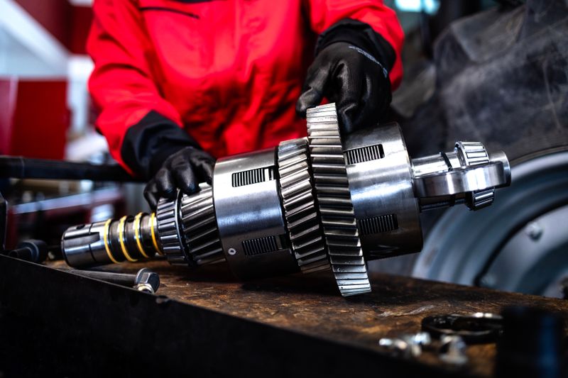
The tractor gearbox was removed for maintenance purposes. (Stock image)
(Source: littlewolf1989 – stock.adobe.com)
Backlash-Free Gearboxes: Improve Positioning Accuracy, Precision, and Controllability of the Drive
Increasing demands for precision, dynamics, and repeatability are increasingly challenging engineers to purposefully minimize gearbox backlash. Particularly in robotics, automation, medical technology, or aerospace, flank clearance often determines the performance of the entire drive system.
Therefore, it is worthwhile to consider the topic of backlash as an independent development parameter already in the concept phase. Reduced backlash not only improves positioning accuracy but also enhances the controllability of the system and ensures more precise power transmission. At the same time, vibrations can be reduced, and the dynamics of the entire system can be improved.
The Beveloid gearing is particularly suitable when minimal flank clearance and high rigidity are required.
(Source: SPN Schwaben Präzision Fritz Hopf)
It is important to note that backlash-free performance is not solely a matter of manufacturing precision. The choice of gearing technology, the design configuration, and the coordination of all components in the gearbox have a significant impact. Therefore, a holistic approach is recommended right from the start of development.
An example of this is the beveloid gearing. This conical spur gearing is particularly suited for applications with high demands for minimal backlash and high rigidity. The opposing cone angles of the gear and pinion allow for targeted control of tooth contact. This ensures high load capacity and precise backlash adjustment—without having to forego the advantages of classic spur gearings.
Modern simulation methods help evaluate different variants before prototype construction and optimize them in terms of load capacity, efficiency, and service life. At the same time, the integration of intelligent sensors is becoming increasingly important. Condition data such as temperature, torque, or vibrations enable continuous monitoring of the gearbox and form the basis for condition-based maintenance.
Conclusion: Those who consider backlash-free performance from the outset and view development, gearing technology, and manufacturing as an integrated system lay the foundation for precise, durable, and economical drive solutions – especially for demanding, customized applications.
Motors: More Torque from Less Installation Space
The axial flux motor W80 AX-Gen offers OEMs new possibilities for implementing compact machine concepts: as the manufacturer WEG has reduced the size of the new motor by around one-third compared to other models, the new motor series allows for a significant reduction in the size of machines and systems. At the same time, downsizing the drive technology lowers logistics costs and reduces CO2 emissions throughout the entire production chain. The motors are available in five frame sizes ranging from IEC 160 to 250, with power outputs between 5.5 and 200 kilowatts (approx. 7.4 to 268 hp)and speeds of 1,500 min-1 to 3,700 or 7,500 min-1 (depending on the frame size).
The new motors require about one-third less installation space.
(Source: WEG Germany)
Since the electromagnetic flux in the axial flux motor runs parallel to the motor's rotational axis, a significantly more compact design is possible. For example, the W80 AX-Gen in the largest frame size measures only about 300 millimeters (approx. 11.8 inches) in length (including the output shaft), with a maximum width of approximately 540 millimeters (approx. 21.3 inches). In this configuration, the motor delivers a torque of up to 637 Newton meters. Even the smallest motor variant, with an overall length of just over 170 millimeters (approx. 6.7 inches), still offers a torque of 33 Newton meters (approx. 24 lb-ft).
At the same time, the material usage is lower than that of comparable radial motors. The series' efficiency also contributes to sustainability, reaching up to 97 percent depending on frame size and power, which corresponds to efficiency class IE5. All models in the family are designed for a constant torque range of 1,000:1 and a constant power range up to 1.3 times the nominal speed.
Prioritize Safety and Safety Components at the Beginning of the Design Phase
A common mistake in the design phase is implementing inadequate safety measures or incorporating them too late in the process. "Often, designers come to me because they are looking for a quick and easy-to-implement solution," reports Maarten Haulet, Sales and Application Engineer at Nexen Europe. "This usually happens after a conversation with their customer, where they were asked whether sufficient safety measures were considered in their design. This can easily be overlooked or underestimated, and now they are under time and cost pressure to find a solution."
Date: 08.12.2025
Naturally, we always handle your personal data responsibly. Any personal data we receive from you is processed in accordance with applicable data protection legislation. For detailed information please see our privacy policy.
Consent to the use of data for promotional purposes
I hereby consent to Vogel Communications Group GmbH & Co. KG, Max-Planck-Str. 7-9, 97082 Würzburg including any affiliated companies according to §§ 15 et seq. AktG (hereafter: Vogel Communications Group) using my e-mail address to send editorial newsletters. A list of all affiliated companies can be found here
Newsletter content may include all products and services of any companies mentioned above, including for example specialist journals and books, events and fairs as well as event-related products and services, print and digital media offers and services such as additional (editorial) newsletters, raffles, lead campaigns, market research both online and offline, specialist webportals and e-learning offers. In case my personal telephone number has also been collected, it may be used for offers of aforementioned products, for services of the companies mentioned above, and market research purposes.
Additionally, my consent also includes the processing of my email address and telephone number for data matching for marketing purposes with select advertising partners such as LinkedIn, Google, and Meta. For this, Vogel Communications Group may transmit said data in hashed form to the advertising partners who then use said data to determine whether I am also a member of the mentioned advertising partner portals. Vogel Communications Group uses this feature for the purposes of re-targeting (up-selling, cross-selling, and customer loyalty), generating so-called look-alike audiences for acquisition of new customers, and as basis for exclusion for on-going advertising campaigns. Further information can be found in section “data matching for marketing purposes”.
In case I access protected data on Internet portals of Vogel Communications Group including any affiliated companies according to §§ 15 et seq. AktG, I need to provide further data in order to register for the access to such content. In return for this free access to editorial content, my data may be used in accordance with this consent for the purposes stated here. This does not apply to data matching for marketing purposes.
Right of revocation
I understand that I can revoke my consent at will. My revocation does not change the lawfulness of data processing that was conducted based on my consent leading up to my revocation. One option to declare my revocation is to use the contact form found at https://contact.vogel.de. In case I no longer wish to receive certain newsletters, I have subscribed to, I can also click on the unsubscribe link included at the end of a newsletter. Further information regarding my right of revocation and the implementation of it as well as the consequences of my revocation can be found in the data protection declaration, section editorial newsletter.
In the later stages of design, implementing safety components becomes more complicated as the scope for changes to the design is significantly limited. Since many components have already been validated, the need for a certified safety solution is crucial.
Safety-certified according to the international safety standard ISO 13849-1: Nexsafe servo brakes from Nexen feature fail-safe mechanical connections to the servo motor and gearbox and can be equipped with up to three sensors.
(Source: Nexen)
The solution to this problem is to prioritize safety and safety components at the beginning of the design phase. "Last-minute changes are always tricky and can lead to delays, as a redesign is required and new components as well as new suppliers need to be identified," says Haulet. "Not all designers are familiar with comprehensive risk analyses, which can result in delayed commissioning of the machines. Components that do not meet the required safety level must be evaluated and classified for these specific situations. These classifications are carried out by specialized companies and lead to additional, unforeseen costs."
The functionally safety-certified servo motor brakes, shaft brakes, and rail brakes from Nexen provide machine builders with a verified solution for designs requiring safety-certified components. With ISO-13849-1 functional safety certification from Intertek, Nexsafe brakes can be used in machines for holding, emergency stop, or positioning applications. "Safety should be a top priority for every company and considered during the design of new machines," says Haulet. "Many companies assure their customers that their products are 'safe,' but lack a classification for higher safety levels, which could have serious consequences for the end user."
Autonomous, mobile robots offer a wide range of applications but pose new safety challenges for engineers, especially in unstructured environments. Unlike in traditional industrial applications, clearly defined processes and rules are lacking here. This makes it all the more important to integrate safety-relevant functions directly into the drive technology.
If actuators feature integrated safety functions, such as torque shutdown, the risks associated with handling the robot are reduced.
(Source: Maxon Motor)
Actuators play a central role in this: they determine how forces are generated and interact with the environment. Their design largely determines whether a robot operates in a controlled and safe manner or poses potential risks to people and infrastructure. Designers should therefore specifically rely on actuators with integrated safety functions. These include, for example, safe torque off, precise speed limitation, defined braking mechanisms, and monitored position and force control.
Especially for mobile systems—such as humanoids or legged robots—compact, lightweight, and highly integrated solutions are required. Traditional redundancies are often not feasible here due to space, weight, or cost constraints. Instead, it is advisable to embed safety directly at the component level. Modern drive solutions, such as those offered by Maxon, demonstrate how functionality and integrated safety mechanisms can be efficiently combined.
For a robust overall solution, however, the close integration of actuators, sensors, and controls is crucial. Actuators should not be considered in isolation but must be embedded in a comprehensive safety concept. Especially in unpredictable environments, a coordinated system architecture is required to detect risks early and trigger appropriate responses.
Despite all measures, a residual risk remains, such as from external influences or unexpected system states. In design, users should therefore focus not only on maximum technical safety but also on controlled malfunctions and defined safe states in the event of a failure.
Conclusion: Those developing autonomous robotic systems should treat actuators as a safety-critical key component. By targeted selection, integration, and safeguarding of drive technology, risks can be significantly reduced while also creating powerful, practical systems.
Author: Mario Mauerer, Business Development Manager Robotics at Maxon Motor GmbH
Periodic Excitation: The Challenge for Safety Couplings in Test Benches
In test benches, high torsional vibration excitations often encounter highly rigid drive components. Piston pumps or highly dynamic test cycles, in particular, generate periodic load changes that differ significantly from standard machine operation. Standard safety couplings increasingly reach their limits in such scenarios.
The cause lies in resonance effects and periodic loads in the drivetrain. These not only increase dynamic stress but also alter the contact conditions within the coupling. In positive-locking safety couplings with a ball-detent mechanism, high-frequency load changes lead to micro-movements on the contact surfaces. This results in running-in and settling processes, which change the contact geometry and the effective preload of the disc spring pack. The consequence is: the disengagement torque drifts.
These effects often occur even with new couplings and only stabilize after a prolonged break-in phase. For test benches, this is critical as reproducible disengagement torques and defined system behavior are prerequisites for reliable measurement results.
For safety couplings used in test benches, the choice of materials is crucial.
(Source: R+W Drive Elements)
Elastic couplings are usually not an alternative for vibration damping. While elastomers reduce vibration amplitudes, they simultaneously decrease the torsional rigidity and modelability of the overall system. This is generally unacceptable for high-precision measurement and synchronization tasks.
An effective alternative is the targeted optimization of material selection within the safety coupling. Through-hardened materials in highly stressed contact areas, such as the mounting flange and shifting ring, significantly reduce running-in and settling effects. Since through-hardened tool steel exhibits high hardness across its entire cross-section, contact mechanics and disengagement torque remain stable and reproducible even under dynamic vibration loads. At the same time, wear is significantly reduced, increasing service life—depending on the application—by a factor of two to ten. For particularly demanding applications, an FEM analysis can help identify critical stresses and deformations at an early stage. This service is, for example, offered by R+W Antriebselemente GmbH.
For designers, this means that in addition to the maximum torque, the vibration behavior of the drivetrain should particularly be considered in the design process. An application-specific choice of materials contributes to functional safety, reproducible disengagement behavior, and the lifespan of the safety coupling.